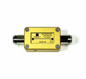
We offer a range of Low Power Fixed and Infinitely Variable Attenuators as well as the range of Laboratory Standard Precision Variable Attenuators.
Waveguide Attenuators - low power
We offer a range of Low Power Fixed and Infinitely Variable Attenuators as well as the range of Laboratory Standard Precision Variable Attenuators. All items are of compact design and are manufactured from brass as standard although copper and aluminium versions are available upon request. The FA and VA series of attenuators are manufactured to the highest quality standards.
Attenuators are manufactured with the full range of International flange styles as shown in flange catalogue and can be offered with alternative plated finishes on request. All our attenuators are offered with attractive hardwearing, epoxy paint finish. Our design and manufacturing facility is approved to ISO 9001: 2008.
Standard Rectangular Fixed Attenuator (Range 0 - 40dB)
Material: Brass
Finish: Blue Paint, Brass Flanges
Full Band Flatness: Nominal 10% attenuator alue (better flatness value can be achieved for narrow band application)
These attenuators use a shaped lossy element attached to the waveguide wall, alternative materials can be used if higher power handling is required - please contact our sales team with details of your requirements.
Operating
Frequency
Band [GHz] | Waveguide
Designation | Max
VSWR | Max
Power
Watts CW | Overall
Length
[A] |
UK
WG | IEC
R | EIA
WR |
| 2.60 - 3.95 | 10 | 32 | 284 | 1.10 | 4 | 330 |
| 3.30 - 4.90 | 11A | 40 | 229 | 1.10 | 4 | 406 |
| 3.95 - 5.85 | 12 | 48 | 187 | 1.12 | 4 | 305 |
| 4.90 - 7.05 | 13 | 58 | 159 | 1.12 | 3 | 280 |
| 5.85 - 8.20 | 14 | 70 | 137 | 1.12 | 2 | 241 |
| 7.05 - 10.0 | 15 | 84 | 112 | 1.13 | 1 | 203 |
| 8.20 - 12.40 | 16 | 100 | 90 | 1.13 | 1 | 152 |
| 10.0 - 15.0 | 17 | 120 | 75 | 1.14 | 1 | 152 |
| 12.4 - 18.0 | 18 | 140 | 62 | 1.14 | 0.7 | 127 |
| 15.0 - 22.0 | 19 | 180 | 51 | 1.15 | 0.7 | 127 |
| 18.0 - 26.5 | 20 | 220 | 42 | 1.15 | 0.5 | 102 |
| 26.5 - 40.0 | 22 | 320 | 28 | 1.20 | 0.5 | 102 |
Attenuation calibration accuracy better than ± 0.35 dB or ± 2.5% (whichever is greater) at the centre frequency.
Ordering: when ordering, please state the attenuation value and frequency.
Double ridged Fixed Attenuator (Range 0 - 40dB)
Material: Aluminium alloy
Finish: Blue Paint, iridited flanges
Full Band Flatness: contact our sales team with details of your requirements.
Attenuation calibration accuracy better than ± 0.6 dB or ±2.5% (whichever is greater) at the centre frequency.
Ordering:- when ordering, please state the attenuation value and frequency.
Please consult our sales team for availability.
Ordering Information
Fixed attenuators
Variable Attenuator (Range 0 - 40dB)
Standard Rectangular
Specification:
Material: Brass
Finish: Blue paint, brass flanges
Attenuation Element: Resistive card
Insertion loss: less than 0.3dB
Full band flatness: contact our sales team with details of your requirements
Note that this attenuator is intended for padder applications and does not come with a calibration chart.
*** For 3 Digit Rectangular Flange part number, refer to the TWS Flange catalogue, or consult the factory.
** Please contact our sales team for availability
Attenuation calibration accuracy better than ±0.35 db at the centre frequency
Variable Precision Attenuator (Range 0 - 40dB)
Standard Rectangular Micrometer Drive
Specification:
Material: Brass
Finish: Blue paint, Brass flanges
Attenuation Element: Resistive card
Insertion loss: less than 0.2dB
Resetting accuracy: ±0.01dB
Full band flatness: Contact our sale team for details
Supplied with a calibration chart
| Operating Frequency Band (GHz) | Waveguide Designation | Max Power Watts C.W. | Micro-meter Resolution dB/div Average | Overall Length “A” (mm) | Dim “B” (mm) |
| UK WG | IEC R | E.I.A. WR |
| **2.60 – 3.95 | 10 | 32 | 284 | 4 | 0.01 | 330 | 267 |
| 3.30 – 4.90 | 11A | 40 | 229 | 4 | 0.02 | 406 | 194 |
| 3.95 – 5.85 | 12 | 48 | 187 | 4 | 0.02 | 305 | 219 |
| **4.90 – 7.05 | 13 | 58 | 159 | 3 | 0.02 | 279 | 200 |
| 5.85 – 8.20 | 14 | 70 | 137 | 2 | 0.03 | 241 | 165 |
| 7.05 – 10.0 | 15 | 84 | 112 | 1 | 0.04 | 203 | 165 |
| 8.20 – 12.40 | 16 | 100 | 90 | 1 | 0.05 | 152 | 127 |
| 10.0 – 15.0 | 17 | 120 | 75 | 1 | 0.05 | 152 | 127 |
| 12.4 – 18.0 | 18 | 140 | 62 | 0.7 | 0.07 | 127 | 120 |
| 18.0 – 26.5 | 20 | 220 | 42 | 0.5 | 0.10 | 102 | 113 |
| 26.5 – 40.0 | 22 | 320 | 28 | 0.2 | 0.07 | 51 | 90 |
Calibration Accuracy
3 Frequencies in Band 0 – 10 dB ± 0.07 dB
1 dB Steps to 10 dB 10 – 20 dB ± 0.1 dB
2 dB Steps to 20 dB 20 – 30 dB ± 0.2 dB
5 dB Steps to 40 dB 30 – 40 dB ± 0.25 dB
** Please contact our sales team for availability
Ordering Information
Variable attenuators
Waveguide Attenuators - medium power
These are constructed from waveguide coupler elements with an load (depending on the power required) on the through arm. They are usually made to customer requirements so please contact our sales team with details of your specifications.
Waveguide Attenuators - high power
High power attenuators use the classic configuration of two 3dB hybrids and a phase shifter. Together with a high and “low” power load, the transmitted power can be infinitely adjusted. The phase shifter is made from twin ganged sliding shorts and 3dB hybrid for maximum power handling. Please contact our sales team with details of your specifications.


