ETL Systems
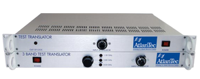
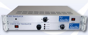
ETL Systems ALT-9800-KA Ka-band Tx to Ka-band Rx, Test Loop Translator - Fixed LO
Request a quote at Contact@orbitalconnect.com or +1.888.315.9545
The ALT series of Ka Band Test Loop Translators (TLTs) are designed to replace the satellite link for test and alignment of earth station systems operating in the Ka frequency bands.
Incorporating fundamental frequency phase locked oscillators and double balanced mixers, the translators block convert frequencies from uplink to either downlink or L-Band for instantaneous monitoring of frequency, power levels and modulation.
The input path contains a front panel controlled continuously variable attenuator for reducing input power levels.
Each unit also provides a reference frequency output and LO lock alarm.
1U high x 19" wide rack mount unit.
Options:
-00 Standard
-01 10MHz Int. Ref.
-02 50MHz Ext. Ref
-03 10MHz Ext. Ref.
-04 OCXO Int. Ref.
-05 TCXO Int. Ref. +/- 1ppm
-06 Programmed LO Frequency
-11 Switched Ext. LO
-12 Exclusive Ext.LO
-13 500MHz Bandwidth
-14 1000MHz Bandwidth
-21 0dB Conversion Gain
-41 Waveguide Input WR28
-42 Waveguide Output WR42
-43 Connectors on Front Panel
Custom Options:
Multi Band Units
Filtered Output
Input and/or Output Isolators (Waveguide)
Modular Construction
Portable Units
Outdoor Units
| General Specification | |||||
| Operating Frequency Range | Input | 27500 - 31000MHz | |||
| Output | 17700 - 21200MHz | ||||
| Maximum Input Level | +10dBm | ||||
| Conversion Gain Flatness | +/-2dB typ. +/-0.5dB/40MHz max | ||||
| Impedance | 50 ohms | ||||
| Input VSWR | 1.8:1 typical | ||||
| Output VSWR | 1.8:1 typical | ||||
| Signal Related Spurious | -25dBc typical | ||||
| LO Related Spurious & Harmonics | -30dBm typical | ||||
| Non Signal or LO Related Spurious | -60dBm minimum | ||||
| Lock Alarm | Front Panel | ||||
| Input Connector (see options) | 2.92mm Female | ||||
| Output Connector | 2.92mm Female | ||||
| Reference Input Connector | BNC Female | ||||
| Power | |||||
| Input Power | 80-240V, 50-60Hz | ||||
| Input Power Connector | IEC with Fuse | ||||
| Environmental | |||||
| Operating Temperature | 0 to +50C (see options) | ||||
| Storage Temperature | -10 to +70C | ||||
| Physical | |||||
| Dimensions | 19” x 1U x 13.5” (343mm) excl. connectors & protrusions | ||||
| Fixed LO Phase Noise dBc/Hz (typical) (GHz) | |||||
| Offset Frequency (Hz) | 2,0 | 10,0 | 12,0 | 27,0 | |
| 100 | -77 | -72 | -70 | -63 | |
| 1K | -90 | -83 | -80 | -75 | |
| 10K | -100 | -85 | -85 | -78 | |
| 100K | -100 | -90 | -85 | -80 | |
| 1M | -132 | -117 | -115 | -109 | |
| 10M | -140 | -138 | -135 | -128 | |


