ETL Systems
ETL Systems CPL10L1P-4307 L-band Directional Coupler DC + 10MHz Pass - 10dB
Request a quote at Contact@orbitalconnect.com or +1.888.315.9545
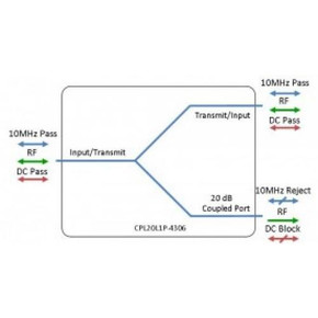
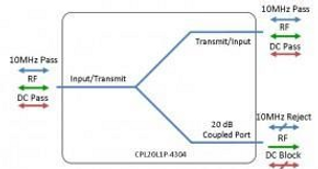
L-band directional Coupler - 10dB with DC and 10MHz pass between input and transmit ports. The coupled port is DC blocked.
Applications: Typical fields of applications are telecom infrastructures, satellite systems, microwave links, test and instrumentation and radar networks.
• DC & 10 MHz pass from input to transmit ports
• Coupled port, DC blocked
Available with RF connector options:
• 50 Ω SMA
• 50 Ω N-type
• 50 Ω BNC
• 75 Ω BNC
• 75 Ω F-type
| RF Parameters | ||||||
| CPL10L1P-4307-XXXXXX | S5S5S5 | N5N5N5 | B5B5B5 | B7B7B7 | F7F7F7 | |
| Frequency Range | 850 - 2150 MHz | |||||
| RF Connectors | 50Ω SMA | 50Ω N-Type | 50Ω BNC | 75Ω BNC | 75Ω F-Type | |
| Through Path : | ||||||
| Mean Insertion Loss (dB) | 1.0 ± 0.2 | 1.0 ± 0.2 | 1.0 ± 0.4 | 1.2 ± 0.4 | 1.2 ± 0.4 | |
| Flatness (dB) | ± 0.5 | ± 0.5 | ± 0.6 | ± 0.6 | ± 0.6 | |
| Input Return Loss (dB) | Typ Min |
20 | 18 | 18 | 12 | 12 |
| 15 | 14 | 14 | 8 | 8 | ||
| Output Return Loss (dB) | Typ Min |
20 | 18 | 18 | 12 | 12 |
| 15 | 14 | 14 | 8 | 8 | ||
| Coupled Port : | ||||||
| Mean Coupling Factor (dB) | 10 ± 1.0 | 10 ± 1.0 | 10 ± 1.0 | 10 ± 1.0 | 10 ± 1.0 | |
| Flatness (dB) | Typ | ± 1.5 | ± 1.5 | ± 1.6 | ± 1.8 | ± 1.8 |
| Return Loss (dB) | Typ Min |
20 | 18 | 18 | 12 | 12 |
| 12 | 12 | 12 | 8 | 8 | ||
| Directivity (dB) | Typ | 14 | 14 | 14 | 14 | 14 |
| 10MHz Insertion Loss is up to 3dB above the theoretical loss* 10MHz Rejection is 20dB* *To ports which are applicable |
||||||
| Max Operating Parameters | |
| Input RF Power | +37 dBm (5W) |
| DC Voltage | 50V |
| DC Current | 3.5A max 5A if N-Type connectors |
| Environmental | |
| Operating Temperature | 0˚C to +45˚C |
| Storage Temperature | -20˚C to +75˚C |
| Location | Indoor use Only |
| Humidity Max | 85% non-condensing |
| Altitude Max | 10,000 feet |


