


WERBEL MICROWAVE
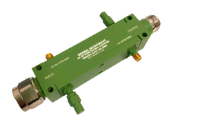
WERBEL MICROWAVE WMHPDDC-1-2-40dB-NS High Power Dual Directional Coupler, 1-2GHz, 40dB, N-F/SMA-F
$880.00

The WMC-0.1-100M-40DB-NS is a broadband 40 dB directional coupler designed for accurate RF power sampling and monitoring from 100 kHz to 100 MHz. Its flat coupling response and low loss through path make it well suited for transmitter monitoring, RF test systems, feedback and protection circuits, industrial RF equipment, and laboratory instrumentation.
Designed to handle up to 200 W peak and 40 W average input power, the coupler provides 0.4 dB maximum insertion loss, 1.2:1 maximum main-line VSWR, 20 dB minimum directivity, and coupling accuracy within ±1 dB. This combination provides reliable measurement performance while minimizing its effect on the primary RF signal.
The compact aluminum enclosure measures approximately 50 x 32 x 22 mm and features N-female connectors on the through line with an SMA-female coupled port. A flat, screw-mountable base supports straightforward installation, while the -15 °C to +55 °C operating temperature range makes the unit suitable for a wide variety of commercial and industrial applications.
| Parameter | Min. | Typ. | Мах. | Unit |
| Frequency Range | 0.1 | - | 100 | MHz |
| Impedance | - | 50 | - | Ω |
| Coupling | - | 40 ± 1.0 | - | dB |
| Frequency Sensitivity (Flatness) | - | ± 0.25 | - | dB |
| Mainline Loss1 | - | 0.1 | 0.4 | dB |
| Directivity | 20 | 28 | - | dB |
| Mainline Return Loss | 20 | 29 | - | dB |
| Secondary Line Return Loss | 20 | 25 | - | dB |
| Isolation | - | 68 | - | dB |
| Average Power2 | - | - | 40 | W |
| Peak Power2 | - | - | 200 | W |
| 1. Mainline loss includes coupling loss. 2. All output ports should be terminated in a 50-ohm load with 1.2:1 max VSWR. |
||||




The WMC-0.1-100M-40DB-NS is a broadband 40 dB directional coupler designed for accurate RF power sampling and monitoring from 100 kHz to 100 MHz. Its flat coupling response and low loss through path make it well suited for transmitter monitoring, RF test systems, feedback and protection circuits, industrial RF equipment, and laboratory instrumentation.
Designed to handle up to 200 W peak and 40 W average input power, the coupler provides 0.4 dB maximum insertion loss, 1.2:1 maximum main-line VSWR, 20 dB minimum directivity, and coupling accuracy within ±1 dB. This combination provides reliable measurement performance while minimizing its effect on the primary RF signal.
The compact aluminum enclosure measures approximately 50 x 32 x 22 mm and features N-female connectors on the through line with an SMA-female coupled port. A flat, screw-mountable base supports straightforward installation, while the -15 °C to +55 °C operating temperature range makes the unit suitable for a wide variety of commercial and industrial applications.
| Parameter | Min. | Typ. | Мах. | Unit |
| Frequency Range | 0.1 | - | 100 | MHz |
| Impedance | - | 50 | - | Ω |
| Coupling | - | 40 ± 1.0 | - | dB |
| Frequency Sensitivity (Flatness) | - | ± 0.25 | - | dB |
| Mainline Loss1 | - | 0.1 | 0.4 | dB |
| Directivity | 20 | 28 | - | dB |
| Mainline Return Loss | 20 | 29 | - | dB |
| Secondary Line Return Loss | 20 | 25 | - | dB |
| Isolation | - | 68 | - | dB |
| Average Power2 | - | - | 40 | W |
| Peak Power2 | - | - | 200 | W |
| 1. Mainline loss includes coupling loss. 2. All output ports should be terminated in a 50-ohm load with 1.2:1 max VSWR. |
||||
| Download Name | |
| WERBEL MICROWAVE WMC-0.1-100M-40dB-NS Datasheet | |
WERBEL MICROWAVE

WERBEL MICROWAVE

WERBEL MICROWAVE

WERBEL MICROWAVE


WERBEL MICROWAVE