




Zoom the image with the mouse
Nisshinbo
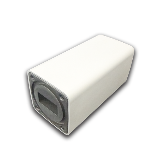
Nisshinbo NJR2845GSF Ku-band PLL LNB 12.2 - 12.75 GHz, Internal Reference
Product Code:
NJR2845GSF
Condition:
New
Availability:
YES
Weight:
0.24 KGS
Width:
8.22
(cm)
Height:
4.00
(cm)
Depth:
4.00
(cm)
Request a quote at Contact@orbitalconnect.com or +1.888.315.9545
About the LNB
The NJR2845GSF is a Nisshinbo low noise block downconverter (LNB) operating in Ku-Band, with an input range of 12.20 - 12.75 GHz, a noise figure of 0.8 dB and an F-type IF interface. Full electrical, mechanical and environmental specifications are listed below.
Key Specifications
| Band | Ku-Band |
| Input Frequency | Ku-Band: 12.20 - 12.75 GHz |
| Noise Figure | 0.8 dB |
| IF Connector | F-Connector |
| Local Stability Line-up | S-type, Internal Reference, Local Stability: +/- 3 ppm |
Electrical Specifications
| Absolute Maximum Rating | RF Input Power: -10 dBm (@ CW) Supply Voltage: +28 V DC |
| Input RF Frequency Range | 12.2 to 12.75 GHz |
| Noise Figure @ +25 °C | 0.8 dB typ., 1.0 dB max. |
| Output IF Frequency Range | 950 to 1,500 MHz |
| Conversion Gain @ +25 °C | 52 dB min., 57 dB typ. |
| Conversion Gain Ripple @ +25 °C | 2 dBp-p max. at any 50 MHz segments. |
| Conversion Gain Flatness over Frequency @ +25 °C | 5 dBp-p max. over Receive Bandwidth |
| Output Power @ 1dB G.C.P. (P1dB) @ +25 °C | 0 dBm min. |
| Output Intercept Point of 3rd Order Intermodulation | +5 dBm min. |
| Tx Signal Immunity | Gain Change: 0.2 dB max. Noise Figure Change: 0.1 dB max. at -20 dBm Tx Input (13.75 to 14.5 GHz) |
| Local Oscillator Frequency | 11.25 GHz nom. |
| Local Oscillator Frequency Stability (-40 to +60 °C) | *Initial Setting Error and Temperature Stability +/-3 ppm max. |
| L.O. Phase Noise (SSB) | -50 dBc/Hz typ. @ 100 Hz -70 dBc/Hz typ. @ 1 kHz -75 dBc/Hz typ. @ 10 kHz -85 dBc/Hz typ. @ 100 kHz -105 dBc/Hz typ. @ 1 MHz In case of E-type, depend on External Reference Stability |
| Requirement for External Reference (Only E-type Specified) | Input Port: IF Output Interface Connector (Combine reference with IF Signal) Frequency: 10 MHz (sine-wave) Input Power: -10 to 0 dBm @IF Output connector Phase Noise: -125 dBc/Hz max. at 100 Hz -135 dBc/Hz max. at 1 kHz -140 dBc/Hz max. at 10 kHz (Input Condition) |
| Spurious | a) -120 dBm max. at input, Fixed frequency spur, unrelated to test CW signal. b) -40 dBc typ., -30 dBc max. with test CW signal -10 dBm IF output |
| Local Oscillator Leakage Levels | -40 dBm max. at the IF Output Connector. -60 dBm max. at the RF Input Flange. |
| Image Rejection | 40 dB min. |
| Input V.S.W.R. | 2.5 : 1 typ. |
| Output Impedance | 75 ohms nom. |
| Output V.S.W.R. | 2.3 : 1 max. |
| Power Requirement | Input Port: IF Output Interface Connector (Combine DC Power with Output IF Signal) Input Voltage: +10 to +24 VDC 170 mA max. |
Mechanical Specifications
| RF Input Interface | Waveguide, WR-75 (with Groove) |
| IF Output Interface | Coaxial Connector, F-type Female - 75 ohms |
| Dimension & Housing | 82.2 (L) x 40 (W) x 40 (H) mm [3.24” (L) x 1.57” (W) x 1.57” (H) ] |
| Weight | 210 g [0.46 lbs] |
Environmental Specifications
| Temperature Range (Ambient) | Operating: -40 to +60 °C Storage: -40 to +80 °C |
| Humidity | 0 to 100 % RH |
| Altitude | 15,000 feet (4,572 m) |
| Vibration (Survival) | 5 G [49.03 m/s2] (3 axis, 50 Hz) |
| Shock (Survival) | 15 G [147.1 m/s2] (3 axis) |
| Waterproof / Dustproof (IP Code Rating) | IP 67 |
| Regulations | EU Directive (CE Marking) RE - 2014/53/EU EMC - 2014/30/EU RoHS - 2011/65/EU + (EU)2015/863 Safety: EN62368-1, EN60950-22 |
| MTBF (by Method of Parts Count Reliability as Design Condition Prediction) | 150,000 hours and more at +60 °C |
5 customers are viewing this product
Details
About the LNB
The NJR2845GSF is a Nisshinbo low noise block downconverter (LNB) operating in Ku-Band, with an input range of 12.20 - 12.75 GHz, a noise figure of 0.8 dB and an F-type IF interface. Full electrical, mechanical and environmental specifications are listed below.
Key Specifications
| Band | Ku-Band |
| Input Frequency | Ku-Band: 12.20 - 12.75 GHz |
| Noise Figure | 0.8 dB |
| IF Connector | F-Connector |
| Local Stability Line-up | S-type, Internal Reference, Local Stability: +/- 3 ppm |
Electrical Specifications
| Absolute Maximum Rating | RF Input Power: -10 dBm (@ CW) Supply Voltage: +28 V DC |
| Input RF Frequency Range | 12.2 to 12.75 GHz |
| Noise Figure @ +25 °C | 0.8 dB typ., 1.0 dB max. |
| Output IF Frequency Range | 950 to 1,500 MHz |
| Conversion Gain @ +25 °C | 52 dB min., 57 dB typ. |
| Conversion Gain Ripple @ +25 °C | 2 dBp-p max. at any 50 MHz segments. |
| Conversion Gain Flatness over Frequency @ +25 °C | 5 dBp-p max. over Receive Bandwidth |
| Output Power @ 1dB G.C.P. (P1dB) @ +25 °C | 0 dBm min. |
| Output Intercept Point of 3rd Order Intermodulation | +5 dBm min. |
| Tx Signal Immunity | Gain Change: 0.2 dB max. Noise Figure Change: 0.1 dB max. at -20 dBm Tx Input (13.75 to 14.5 GHz) |
| Local Oscillator Frequency | 11.25 GHz nom. |
| Local Oscillator Frequency Stability (-40 to +60 °C) | *Initial Setting Error and Temperature Stability +/-3 ppm max. |
| L.O. Phase Noise (SSB) | -50 dBc/Hz typ. @ 100 Hz -70 dBc/Hz typ. @ 1 kHz -75 dBc/Hz typ. @ 10 kHz -85 dBc/Hz typ. @ 100 kHz -105 dBc/Hz typ. @ 1 MHz In case of E-type, depend on External Reference Stability |
| Requirement for External Reference (Only E-type Specified) | Input Port: IF Output Interface Connector (Combine reference with IF Signal) Frequency: 10 MHz (sine-wave) Input Power: -10 to 0 dBm @IF Output connector Phase Noise: -125 dBc/Hz max. at 100 Hz -135 dBc/Hz max. at 1 kHz -140 dBc/Hz max. at 10 kHz (Input Condition) |
| Spurious | a) -120 dBm max. at input, Fixed frequency spur, unrelated to test CW signal. b) -40 dBc typ., -30 dBc max. with test CW signal -10 dBm IF output |
| Local Oscillator Leakage Levels | -40 dBm max. at the IF Output Connector. -60 dBm max. at the RF Input Flange. |
| Image Rejection | 40 dB min. |
| Input V.S.W.R. | 2.5 : 1 typ. |
| Output Impedance | 75 ohms nom. |
| Output V.S.W.R. | 2.3 : 1 max. |
| Power Requirement | Input Port: IF Output Interface Connector (Combine DC Power with Output IF Signal) Input Voltage: +10 to +24 VDC 170 mA max. |
Mechanical Specifications
| RF Input Interface | Waveguide, WR-75 (with Groove) |
| IF Output Interface | Coaxial Connector, F-type Female - 75 ohms |
| Dimension & Housing | 82.2 (L) x 40 (W) x 40 (H) mm [3.24” (L) x 1.57” (W) x 1.57” (H) ] |
| Weight | 210 g [0.46 lbs] |
Environmental Specifications
| Temperature Range (Ambient) | Operating: -40 to +60 °C Storage: -40 to +80 °C |
| Humidity | 0 to 100 % RH |
| Altitude | 15,000 feet (4,572 m) |
| Vibration (Survival) | 5 G [49.03 m/s2] (3 axis, 50 Hz) |
| Shock (Survival) | 15 G [147.1 m/s2] (3 axis) |
| Waterproof / Dustproof (IP Code Rating) | IP 67 |
| Regulations | EU Directive (CE Marking) RE - 2014/53/EU EMC - 2014/30/EU RoHS - 2011/65/EU + (EU)2015/863 Safety: EN62368-1, EN60950-22 |
| MTBF (by Method of Parts Count Reliability as Design Condition Prediction) | 150,000 hours and more at +60 °C |
Related Products